

Custom Search
|
|

|
||
 TM 5-685/NAVFAC MO-912
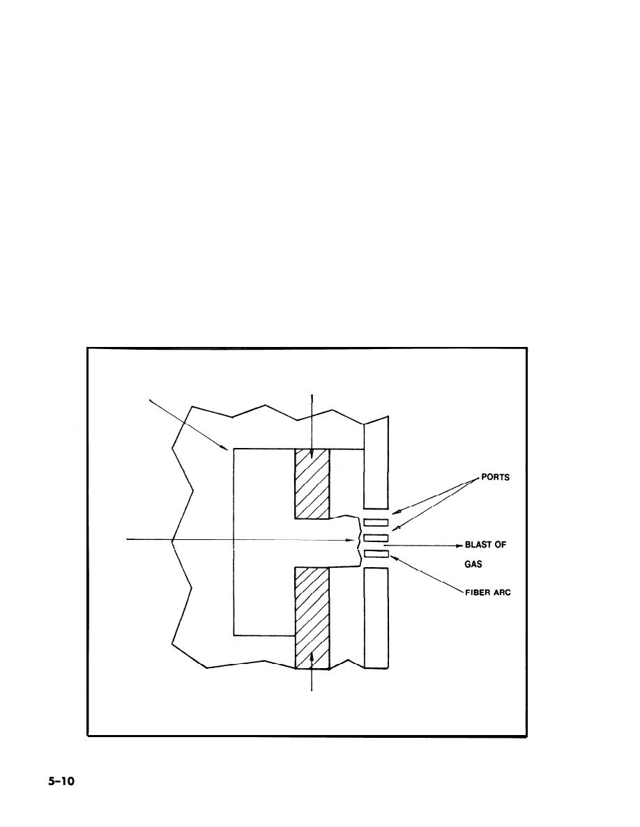
(1) Oil circuit b reakers. When the contacts are
high-pressure air is directed across the arc pushing
separated in oil, the interrupted voltage and cur-
the arc against the splitter. The arc is broken at
rent can be greater as compared to contact separa-
current zero and carried downstream.
tion in air at room temperature.
(3) Vacuum circuit breakers. Vacuum arc inter-
(a) Arc interruption is better in oil than air
ruption is the newest and quickest method of extin-
because the dielectric strength of oil is much greater
guishing an electric arc. This type of breaker (see
than air. Also, the arc generates hydrogen gas from
figure 5-11) is oil-less, fireproof and nearly mainte-
the oil (see fig 5-9). The gas is superior to air as a
nance free. Service life is very long. Arc interruption
cooling medium.
is very rapid, usually in the first current zero. High
(b) Usually the contacts and the arc are en-
dielectric strength of a small vacuum gap contrib-
closed in a fiber arcing chamber, with exhaust ports
utes to the rapid interruption of the arc. Short con-
on one side, to increase the capacity.
tact travel permits the mechanism to part the con-
(2) Air circuit breakers. Arc extinction by high
tacts much faster than for oil breakers.
pressure air blast is another method of quickly in-
(4) Warning. Mechanical indication of "open"
terrupting and extinguishing electric arc. Cross-
may not be true. Always make sure no voltage exists
blast type breakers are usually used in medium
on load/line side before performing any work.
voltage switchgear.
(a) A cross-blast breaker uses an arc chute
former (PT) is an accurately wound, low voltage-loss
with one splitter (insulating fin) that functions as
instrument transformer having a fixed primary to
an arc barrier (see fig 5-10).
secondary "step down" voltage ratio. The PT is
(b) The arc is drawn between the upper and
mounted in the high voltage enclosure and only the
lower electrodes. During interruption, a blast of
low voltage leads from the secondary winding are
STATIONARY
FIBER WALLS
CONTACT
FORMING ARCING
CHAMBER
ARC
SPLITTERS
MOVING
CONTACT
Figure 5-9. Arc interruption in oil, diagram.
|
 |
|
|
||


